ARCH 614 Note Set 124 S2013abn 2. Example Description Code MWFRS Type CC Type Page Preface 3 ASCE 7-16 Summary of Major Changes 5 11a Manufacturing Building. Asce 7 10 design examples
Asce 7 10 Design Examples, Company JOB TITLE Example 10 - Sign Address City State JOB NO. Positive external pressure on the bottom surface of windward roof overhangs shall be determined using Cp 08 and combined with the top surface pressure of roof. Importance factors Ie are shown in ASCE 7-10 Table 15-2. The examples provided have been created using VCmaster.
 Mecawind Ebook From engineering-software.com
ASCESEI 7-10 is not retroactive and usually applies to exist-ing structures only when there is an addition change of use or alteration. Lets assume our project is in Madison Wisconsin and we have already calculated our balanced roof snow load here. From our example our ground load and flat roof snow load were found to be 30 psf and 21 psf respectively. This is a term used by ASCE 7 to define the tributary area for the element or component being considered for wind design.
Main Wind Force Resisting System Method 2 h 60 ft.
Read another article:
Positive external pressure on the bottom surface of windward roof overhangs shall be determined using Cp 08 and combined with the top surface pressure of roof. SkyCiv released a free wind load calculator that has several code references including the ASCE 7-10 wind load procedure. Fpx 02SDS Iewpx minimum ASCE 7 1210-2 The diaphragm design force need not exceed. ARCH 614 Note Set 124 S2013abn 4. Walls Roofs Windward Case B Figure 286-1.
 Source: engineeringexpress.com
5301-02ASCE 6-02TMS 602-02 ASCESEI 7-10 Minimum Design Loads for Buildings and Other Structures SEIASCE 8-02 Standard Specifi cation for the Design of Cold-Formed Stainless Steel Structural Members ANSIASCE 9-91 listed with ASCE 3-91 ASCE 10-97 Design of Latticed Steel Transmission Structures SEIASCE 11-99 Guideline for Structural. Design Philosophy Seismic-Force-Resisting System SFRS that provides a complete load path is required. Fpx 04SDS Iewpx maximum ASCE 7 1210-3 where. ASCE 7-10 Wind Provisions and Effects on Wood Design and Construction Philip Line PE1 William L. How Do I Calculate The Effective Opening Area On Window Or Door Products What Opening Area Should Be Used For Wind Pressure Determination On A Multi Panel Product Engineering Express.
 Source: studylib.net
Source: studylib.net
The design wind pressure shall be calculated as. From our example our ground load and flat roof snow load were found to be 30 psf and 21 psf respectively. Fpx 02SDS Iewpx minimum ASCE 7 1210-2 The diaphragm design force need not exceed. Importance factors Ie are shown in ASCE 7-10 Table 15-2. Most Common Errors In Seismic Design Under Asce 7.
 Source: engineering-software.com
ASCE 7-10 Wind Provisions and Effects on Wood Design and Construction Philip Line PE1 William L. ARCH 614 Note Set 124 S2013abn 4. Interactive design aids in accordance to US codes ACI 318-11 AISC 14th edition and ASCE-7-10 Guidelines of use After installing a free trial or demo version the interactive templates will be available free of charge. ARCH 614 Note Set 124 S2013abn 5. Mecawind Ebook.
 Source: structuremag.org
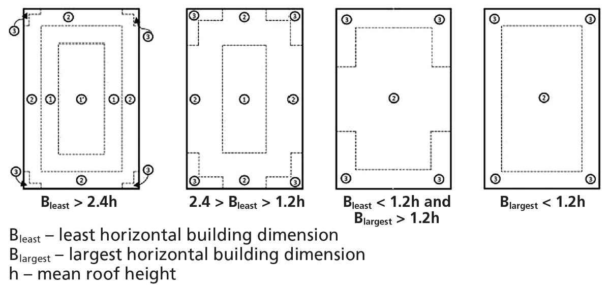
Minimum acceptable seismic resistance of existing buildings is a policy issue normally set by the authority having jurisdiction. Structures classified as Risk Category I II or III that are located where the mapped spectral response acceleration parameter at 1-second period S1 is greater than or equal to 075 shall be assigned to Seismic Design Category E. I am in the process of designing a small free-standing canopy 8 ft x 35 ft 8-0 high. Minimum acceptable seismic resistance of existing buildings is a policy issue normally set by the authority having jurisdiction. Structure Magazine Asce 7 16 Wind Load Provisions.

Company JOB TITLE Example 10 - Sign Address City State JOB NO. Load combinations specified in ASCE 7-16 Section 23 and 24 are used for design. ASCE 7-10 calculations are based on 700-year return period three second gust wind speeds corresponding to an ap-proximate 7 probability of exceedence in 50 years and use combined gust and pressure coefficients to translate these wind speeds into peak design pressures on the struc - ture. Calculation of Wind Loads on Structures according to ASCE 7-10 Permitted Procedures The design wind loads for buildings and other structures including the Main Wind-Force Resisting System MWFRS and component and cladding elements thereof shall be determined using one of the procedures as specified in the following section. Woodworks Org.
 Source: civilengineeringbible.com
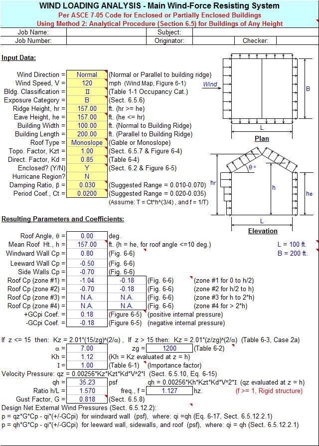
ASCE 7 uses EWA sizes of 10 20 50 100 200 500 and 1000 sq. 75 wind loads in two perpendicular directions simultaneously. SteelPE Structural OP 10 Apr 19 2106. Design Methods For all seismic isolation designs necessary to first perform static analysis Static Analysis establishes minimum level for design displacements and forces Static analysis or equivalent lateral force procedure can be used as only. Wind Loading Calculator Sheet Per Asce 7 05 Code Civilengineeringbible Com.
 Source: studylib.es
Source: studylib.es
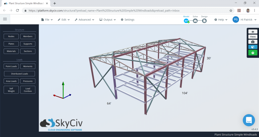
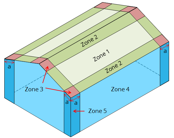
Chapter 7 ASCE 7-10 Design Provisions for Structures with Passive Energy Dissipating Systems 2. In this section we are going to demonstrate how to calculate the wind loads by using an S3D warehouse model below. Lets assume our project is in Madison Wisconsin and we have already calculated our balanced roof snow load here. Example Description Code MWFRS Type CC Type Page Preface 3 ASCE 7-16 Summary of Major Changes 5 11a Manufacturing Building. Asce 7 10.
 Source: skyciv.com
75 wind loads in two perpendicular directions simultaneously. Load combinations specified in ASCE 7-16 Section 23 and 24 are used for design. Design code is IBC 2015ASCE7-10. ARCH 614 Note Set 124 S2013abn 2. Asce 7 10 Wind Load Calculation Example Skyciv Engineering.
 Source: skyciv.com
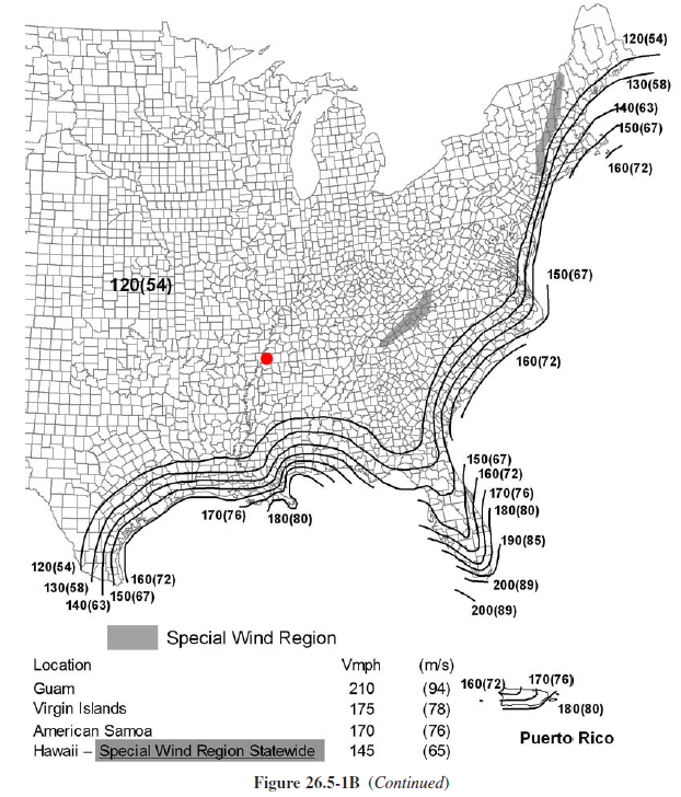
This is a term used by ASCE 7 to define the tributary area for the element or component being considered for wind design. 07 in combination with the top surface pressures determined using Fig. Chapter 7 ASCE 7-10 Design Provisions for Structures with Passive Energy Dissipating Systems 2. MASCE2 ABSTRACT It is well known that the major change for wind design in ASCE 7-10 Minimum Design Loads for Buildings and Other Structures is the introduction of new wind speed maps that are referred to as ultimate wind speed maps in the 2012. Asce 7 10 Wind Load Calculation Example Skyciv Engineering.
 Source: engineering-software.com
ARCH 614 Note Set 124 S2013abn 2. See Figure 7-7 from ASCE 7-10 below for a succinct depiction. ARCH 614 Note Set 124 S2013abn 4. ASCE 7 uses EWA sizes of 10 20 50 100 200 500 and 1000 sq. Mecawind Ebook.
 Source: engineersedge.com
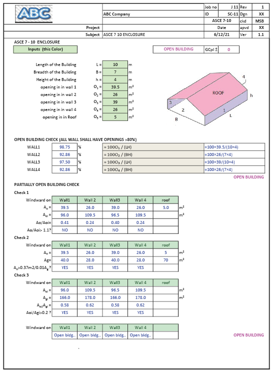
ARCH 614 Note Set 124 S2013abn 2. 35 ft wide x 70 ft long x 15 ft tall with flat roof. Structures classified as Risk Category I II or III that are located where the mapped spectral response acceleration parameter at 1-second period S1 is greater than or equal to 075 shall be assigned to Seismic Design Category E. ASCESEI 7-10 is not retroactive and usually applies to exist-ing structures only when there is an addition change of use or alteration. Partially Open Building Wind Loads Asce 7 10 Spreadsheet Calculator Engineering Excel Spreadsheet Calculators.
 Source: skyciv.com
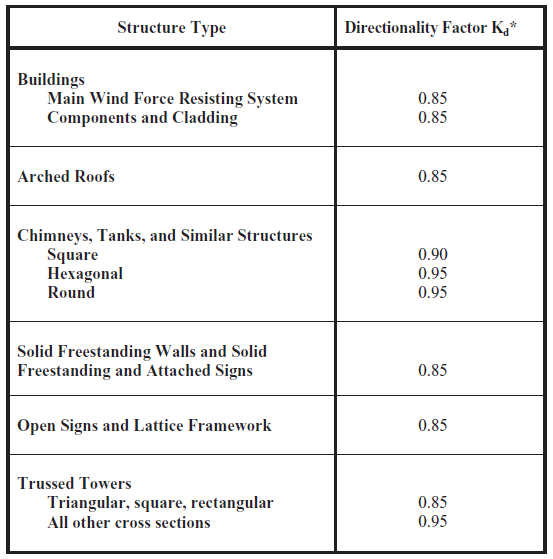
Company JOB TITLE Chapter 5 examples Address City State JOB NO. 75 wind loads in two perpendicular directions simultaneously. Roof slope is 112. See Figure 7-7 from ASCE 7-10 below for a succinct depiction. Asce 7 10 Wind Load Calculation Example Skyciv Engineering.
 Source: skyciv.com
Damping of SFRS modified by damping devices. 2844 Minimum Design Wind Loads The wind load to be used in the design of the MWFRS for an enclosed or partially enclosed building shall not be less than 16 lbft2 077 kNm2 Table 282-1 Steps to Determine Wind Loads on MWFRS Low-Rise Buildings. Load combinations specified in ASCE 7-16 Section 23 and 24 are used for design. From our example our ground load and flat roof snow load were found to be 30 psf and 21 psf respectively. Asce 7 10 Wind Load Calculation Example Skyciv Engineering.
 Source: structuremag.org
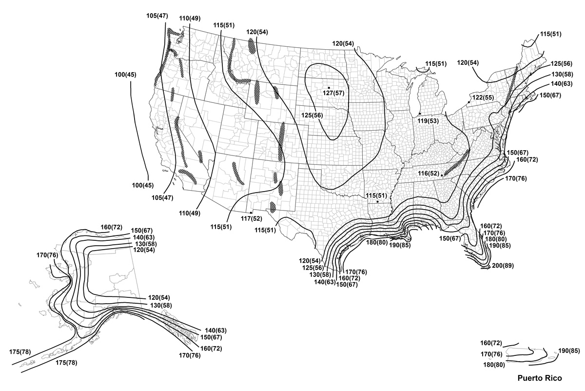
2844 Minimum Design Wind Loads The wind load to be used in the design of the MWFRS for an enclosed or partially enclosed building shall not be less than 16 lbft2 077 kNm2 Table 282-1 Steps to Determine Wind Loads on MWFRS Low-Rise Buildings. I am in the process of designing a small free-standing canopy 8 ft x 35 ft 8-0 high. Load combinations specified in ASCE 7-16 Section 23 and 24 are used for design. This is a term used by ASCE 7 to define the tributary area for the element or component being considered for wind design. Structure Magazine Asce 7 16 Wind Load Provisions.
 Source: skyciv.com
75 wind loads in two perpendicular directions simultaneously. ASCE 7-10 Wind Provisions and Effects on Wood Design and Construction Philip Line PE1 William L. A fully worked example of ASCE 7-10 wind load calculations. ARCH 614 Note Set 124 S2013abn 4. Asce 7 10 Wind Load Calculation Example Skyciv Engineering.


