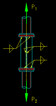
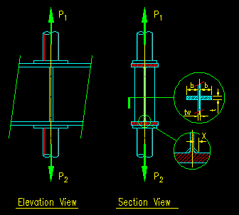
Use 70 ksi electrode welds to connect the stiffener and top angle. I found an example somewhat similar to this in Blodgett on page 33-25 and 33-26. Bearing stiffener design example
Bearing Stiffener Design Example, There may also be horizontal loading to consider from the bracing which may generate bending moments in the stiffener section. A A w 0 1 2 N Ed N Ed adjacent transverse stiffeners stiffener. Typically a member taller than the minimum will be the most efficient. The web for example above a knuckle bearing which is providing torsional restraint to the main girder Tee stiffeners may be specified but this does add considerably to the task of welding and This example will illustrate the procedures to design a steel beam to BS 5400 Part 3.
 Bearing And Stiffener Design For Steel Beams Sd424 Youtube From youtube.com
Overview of key contents of EN 1993. Design a stiffened seated connection between a W2168 beam and a W1490 column flange to support the following end reactions. B 19 in. The example is of a stiffened base plate.
Design of Bearing stiffeners in accordance with CSA S16.
Read another article:
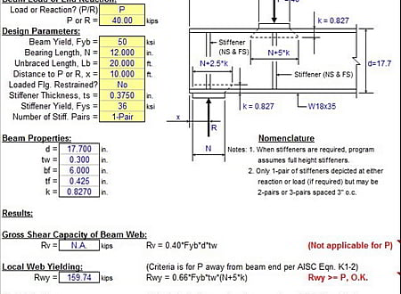
Web Yielding Crippling Buckling and Stiffener Criteria for Concentrated Load or Reaction Per AISC 9th Edition Manual ASD. It is advisable to design the connection between such stiffeners and the flange to resist the tensile force due to the change of direction of the flange plate ignoring the bearing reaction. RD 21 kips RL 625 kips Use w in. B 19 in. Partial depth stiffener are allowed.
 Source: cesdb.com
This will cater for situations where the load path from the bearing does not spread to the stiffener as a result of extreme thermal movement and. It is advisable to design the connection between such stiffeners and the flange to resist the tensile force due to the change of direction of the flange plate ignoring the bearing reaction. Since the Mpl is expressed in units of kip-inin the plate thickness expressions can be formatted with-out the plate width B as such. A sample analytical method for bearing resistance calculation. Stiffner Steel Beam Web Stiffener Analysis Spreadsheet.
 Source: pinterest.com
Typically a member taller than the minimum will be the most efficient. Design of steel bridges. Conc rete deck steel plate girder bolted field splice shear connectors bearing stiffeners welded connections elastomeric bearing cantilever abutment and wingwall hammerhead pier and pile foundations. SCM G22 describes the criteria for the design of the actual stiffeners. Pin On Structuraldetails Store Catalogue.
 Source: researchgate.net
Stiffener plates can be applied to either just one side of the web or both sides. Illustrated through the design example presented herein. In no case should the steel section be less than 00285L unless approved by the Bridge Design Engineer. The example illustrates the design of a typical three-span continuous straight steel I-girder bridge with spans of 1400 feet 1750 feet 1400 feet. Bio Inspired Design Of Stiffener Plate Distribution In A Machine Tool Bed Download Scientific Diagram.
 Source: pinterest.com
RD 21 kips RL 625 kips Use w in. The pad eye thickness at the hole shall not be less than 75 the inside width of the shackle sect 16954 Rm 2 Rc1 2 Rc2 mm NOT OK 075 x e mm 4. The objective is to select the thickness t and width b of the stiffener plates. Overview of key contents of EN 1993. Steel Beam Design London Steel Beam Installation Steel Beams Beams Design.
 Source: youtube.com
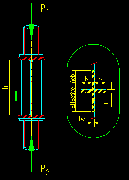
The force to a single stiffener plate is half of the above. This will cater for situations where the load path from the bearing does not spread to the stiffener as a result of extreme thermal movement and. To make this reference user-friendly the numbers and titles of the design steps are consistent between the. The total thicknesses of cheek plates on one side of the main plate should not exceed 100 sect 16955 of the main plate thickness. Design Of Stiffeners And Non Concentric Brace Connections With Risaconnection V3 Youtube.
 Source: bgstructuralengineering.com
This assumes that the spacing. Stiffener Design for Web Crippling. T track thickness F ut track yield strength e design gap for deflection Ω 28 for ASD Φ 055 for LRFD F ut 045 for LSD α 10 when e t and stud spacing are. I 250156 3 12 10250 3 12 13110 6 mm 4 δ t 17442 3 320500013110 6 5110 -6 mmN. Bearing Stiffeners.
 Source: pinterest.com
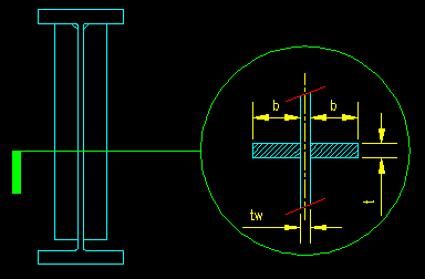
The plate and the flange will act like a T section. Design of Bearing stiffeners in accordance with CSA S16. Conc rete deck steel plate girder bolted field splice shear connectors bearing stiffeners welded connections elastomeric bearing cantilever abutment and wingwall hammerhead pier and pile foundations. Partial depth stiffener are allowed. Pin On تفاصيل المصعد.
 Source: pinterest.com
I found an example somewhat similar to this in Blodgett on page 33-25 and 33-26. In no case should the steel section be less than 00285L unless approved by the Bridge Design Engineer. Stiffener plates can be applied to either just one side of the web or both sides. A A w 0 1 2 N Ed N Ed adjacent transverse stiffeners stiffener. Baseplate Detail Steel Heb 240 Column Section Steel Columns Steel Trusses Concrete Footings.
 Source: sciencedirect.com
Partial depth stiffener are allowed. RD 21 kips RL 625 kips Use w in. T track thickness F ut track yield strength e design gap for deflection Ω 28 for ASD Φ 055 for LRFD F ut 045 for LSD α 10 when e t and stud spacing are. Web Yielding Crippling Buckling and Stiffener Criteria for Concentrated Load or Reaction Per AISC 9th Edition Manual ASD. Stiffener An Overview Sciencedirect Topics.
 Source: bgstructuralengineering.com
Typically a member taller than the minimum will be the most efficient. February 7 2017 2 Likes 2 Comments. SAMPLE CALCULATION Using AISI Wall Stud Design standard AISI S211-07 Calculate the nominal strength of a single deflection track subjected to transverse loads. Illustrated through the design example. Bearing Stiffeners.
 Source: bgstructuralengineering.com
SCM G22 describes the criteria for the design of the actual stiffeners. This will cater for situations where the load path from the bearing does not spread to the stiffener as a result of extreme thermal movement and. Determine the length of bearing. Published on February 7 2017. Web Stiffeners.
 Source: pinterest.com
Specifically web yielding web crippling and web buckling criteria are checked to determine if web stiffeners are required to resist the concentrated load. Overview of key contents of EN 1993. T track thickness F ut track yield strength e design gap for deflection Ω 28 for ASD Φ 055 for LRFD F ut 045 for LSD α 10 when e t and stud spacing are. Reqd Connection Capacity to bottom flange P 2 - Capacity of W section. Steel Portal Frames Vertical Chs X Bracing Details Steel Columns Steel Trusses Steel Roofing.
 Source: pinterest.com
Since the Mpl is expressed in units of kip-inin the plate thickness expressions can be formatted with-out the plate width B as such. Nutte Structural 25 Jan 12 1135. In either case the stiffeners must provide sufficient moment of inertia to prevent out of plane buckling. If playback doesnt. Baseplate Detail Steel Heb 240 Column Section Steel Columns Steel Trusses Concrete Footings.
 Source: youtube.com
SCM G22 describes the criteria for the design of the actual stiffeners. The example illustrates the design of a typical three-span continuous straight steel I-girder bridge with spans of 1400 feet 1750 feet 1400 feet. SAMPLE CALCULATION Using AISI Wall Stud Design standard AISI S211-07 Calculate the nominal strength of a single deflection track subjected to transverse loads. Overview of key contents of EN 1993. Bearing And Stiffener Design For Steel Beams Sd424 Youtube.
 Source: bgstructuralengineering.com
Design of end bearing stiffener in steel structure. Design example includes detailed design computations for the following bridge features. To make this reference user-friendly the numbers and titles of the design steps are consistent between the. Illustrated through the design example. Bearing Stiffeners.


