This section introduces the dimension calculations for spur gears helical gears gear rack bevel gears screw gears and worm gear pairs. This calculator determines bevel gear and pinion parameters. Bevel gear design calculation pdf
Bevel Gear Design Calculation Pdf, The smallest gear is referred to as a pinion and the larger gear is referred to as gear. Calculation of gear ratio i and pitch angle Selection of material. Design of Bevel Gear - Free download as Powerpoint Presentation ppt pptx PDF File pdf Text File txt or view presentation slides online. The following table Table 1 is presenting the formulas t hat are used to calculate the blank and.
 Worm And Wormgear Design Equations And Calculator Worms Equations Mechanical Design From pinterest.com
Quick-View shows calculation results together with bevel gear drawings altogether on one screen. 20 for the nomenclature of a meshed bevel gear. Nomenclature of a meshed bevel gear Source. Select the diametral pitch with units of teeth per distance and then select the number of teeth for each.
X To design and modeling of bevel gear and pinion assembly.
Read another article:
Calculation of gear ratio i and pitch angle. Bevel gears are used for drives requiring the input shaft to be at an angle usually 90 to the output shaft. This PPT contains 1. Basically KHK stock bevel gears should be selected as shown in the catalog in pairs eg. Calculation of gear ratio i and pitch angle.
 Source: semanticscholar.org
X To design and modeling of bevel gear and pinion assembly. The sum of the pitch angles of spiral bevel gears is equal to the shaft angle. The approach utilizes standard design equations and standard data on. You cannot install bevel gears in the same manner as spur and helical gears and expect them to behave and perform as well. Pdf Design And Analysis Of A Spiral Bevel Gear Semantic Scholar.
 Source: mdpi.com
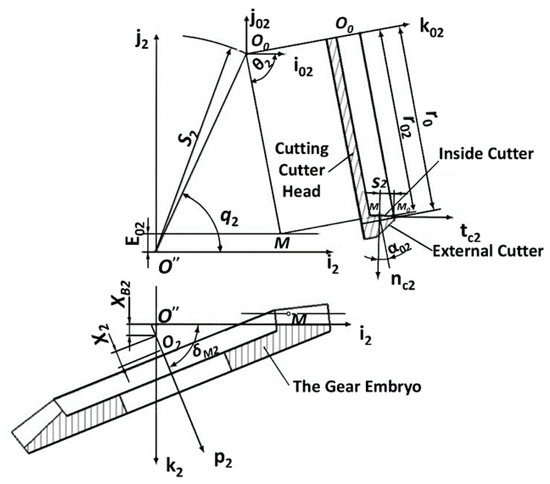
Strength Calculation The safety margins against root fatigue fracture pitting and seizure are determined in the strength calculation acc. Calculation of gear ratio i and pitch angle. Gear theory terminology selection of gear size tooth design parameters and cutting methods. In this chapter the geometry of the main types of spiral bevel gears is first defined and considerations about the spiral angle are made and two approaches to theoretical analysis are described capable to provide reliable results in terms of geometric and kinematic characteristics of these types of gears. Applied Sciences Free Full Text Theoretical And Experimental Study On Contact Characteristics Of Spiral Bevel Gears Under Quasi Static And Large Loading Conditions Html.
 Source: mdpi.com
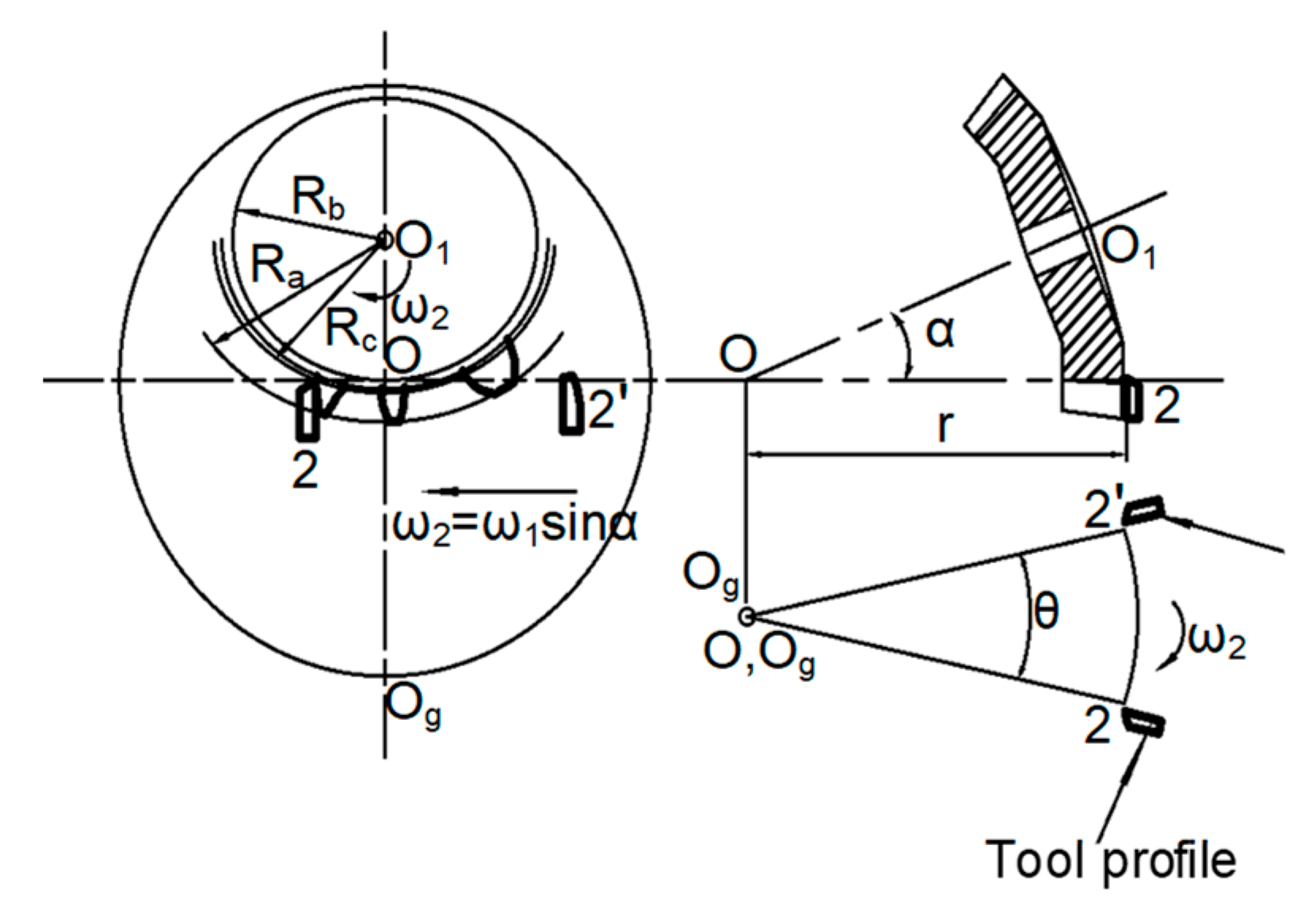
PDF This paper prescribes a Computer Aided approach to the design of bevel gears. DESIGN OF BEVEL GEARS Bevel gears are designing for which calculating the required traction force and for keep ing a system compact bevel gears are designed by minimum requirement number of teeth. Input Parameters Gear type - according to the position of root and head cone Gear ratio and tooth numbers Pressure angle the angle of tool profile α t Helix angle β m Axis angle Σ Tangential module on outer cone met for metric calculation Tangential Diametral Pitch on outer cone Pet for English units Note. X To design and modeling of bevel gear and pinion assembly. Metals Free Full Text Design And Simulation Of Meshing Performance Of Modified Straight Bevel Gears Html.
 Source: semanticscholar.org
Design procedure for Bevel Gear. This section introduces the dimension calculations for spur gears helical gears gear rack bevel gears screw gears and worm gear pairs. Nomenclature of a meshed bevel gear Source. There are available specifications for scuffing calculation as well as technical reports for sample calculations. Pdf Stress Analysis Of Bevel Gear Tooth Using Fea A Review Semantic Scholar.
 Source: roymech.org
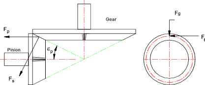
Pressure angles of gearsets are standardized at a few values by the gear manufacturers. Tooth dimensions of spriral bevel gears according to ANSIAGMAISO standards 3 4 7. Bevel gears are used for drives requiring the input shaft to be at an angle usually 90 to the output shaft. As the popularity of five-axis CNC machine tools and multi-axis CAM software has increased such tools are now being used to manufacture these types of gears in small size lots. Bevel Gears Roy Mech.
 Source: pinterest.com
Strength Calculation The safety margins against root fatigue fracture pitting and seizure are determined in the strength calculation acc. Nomenclature of a meshed bevel gear Source. Introduction to Gear Design Introduction Albert Einstein once said. Module and Diametral Pitch are reciprocal values. Worm And Wormgear Design Equations And Calculator Worms Equations Mechanical Design.
 Source: researchgate.net
The following table lists the main features for easy selection. Bevel gears can include straight spiral Zerol hypoid and. They can be cut with either straight teeth where the same comments as for spur gears apply or they can be cut spiral which correspond to the helical type of parallel gearing. Load calculation of gears 233 113 Calculation of load on spiral bevel gears In the case of spiral bevel gears the magnitude and direction of loads at the meshing point vary depending on the running direction and gear twist direction. Concept Of Spiral Bevel Gear Hobbing Download Scientific Diagram.
 Source: pdf.directindustry.com
Calculation of gear ratio i and pitch angle. Calculation of gear ratio i and pitch angle. Formative number of teeth 4. The sum of the pitch angles of spiral bevel gears is equal to the shaft angle. Bevel Gearing Quality Transmission Components Pdf Catalogs Technical Documentation Brochure.

Bevel Gear Technology Chapter 2. Tooth dimensions of spriral bevel gears according to ANSIAGMAISO standards 3 4 7. The smallest gear is referred to as a pinion and the larger gear is referred to as gear. Bevel Gear Technology Chapter 2. Bevel Pdf Gear Mechanics.
 Source: sciencedirect.com
As the popularity of five-axis CNC machine tools and multi-axis CAM software has increased such tools are now being used to manufacture these types of gears in small size lots. Formative number of teeth 4. Basically KHK stock bevel gears should be selected as shown in the catalog in pairs eg. The objective of this project was to develop an automated process for modeling spiral bevel gears to reduce gear design time. Bevel Gears An Overview Sciencedirect Topics.
 Source: semanticscholar.org
Design a pair of bevel gear which is used to connect two shaft at right angles and transmit P 50 kW power from an induction motor to a conveyor belt. The following table lists the main features for easy selection. Design procedure for Bevel Gear. Things should be made as simple as possible but no simpler This book is an attempt to apply that principle to gear design by presenting information from a manufacturing point-of-view rather than a theoretical one. Pdf Design And Analysis Of A Spiral Bevel Gear Semantic Scholar.
 Source: link.springer.com
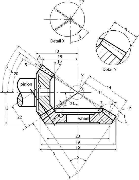
KHK stock bevel gears are available in two types spiral and straight tooth in gear ratios of 15 through 5 and are offered in a large va- riety of modules numbers of teeth materials and styles. Where NA and NB speed of the driver and driven respectively and ZA and ZB Number of teeth on driver and driven respectively. The running is either clockwise or counterclockwise as viewed from the side opposite of the gears Fig. KHK stock bevel gears are available in two types spiral and straight tooth in gear ratios of 15 through 5 and are offered in a large va- riety of modules numbers of teeth materials and styles. Fundamentals Of Bevel Gears Springerlink.

The smallest gear is referred to as a pinion and the larger gear is referred to as gear. KMBSG2-4020R should mate with KMBSG2-2040L. Design of Bevel Gear - Free download as Powerpoint Presentation ppt pptx PDF File pdf Text File txt or view presentation slides online. Strength Calculation The safety margins against root fatigue fracture pitting and seizure are determined in the strength calculation acc. Help Bevel Gear Generate Autodesk Community Inventor.
 Source: semanticscholar.org
Where NA and NB speed of the driver and driven respectively and ZA and ZB Number of teeth on driver and driven respectively. Strength Calculation The safety margins against root fatigue fracture pitting and seizure are determined in the strength calculation acc. A bevel gear is shaped like a section of a cone. Bevel Gear Technology Chapter 2. Pdf Design And Analysis Of A Spiral Bevel Gear Semantic Scholar.
 Source: khkgears.net
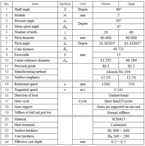
Calculation of gear ratio i and pitch angle. Speed of pinion and gear are Np 500 RPM and Ng 250 RPM respectively. Exercises in calculating gear dimension sheets the use of Gleason time sharing computer programs and the evaluation of resulting stress data. It assumes 90 degree angle between the gears. Bending Strength Of Bevel Gears Khk Gears.


