The voltage g - Sarthaks eConnect Largest Online Education Community. A common emitter amplifier is designed with NPN transistor alpha099. A common emitter amplifier is designed with npn transistor.
A Common Emitter Amplifier Is Designed With Npn Transistor, Common emitter configuration can be applied on both types of transistor PNP transistor and NPN transistor. The voltage g - Sarthaks eConnect Largest Online Education Community. It will be enough to call t. Lets take a closer look at common-emitter transistor amplifiers and discuss some things designers should consider during the common-emitter transistor.
 Proud To Be An Electronics Engineer Electronic Engineering Transistors Electronics From br.pinterest.com
Well basically Grounding in this case just means the point in the circuit the designer decided to call zero volts and use as a reference voltage when measuring voltages elsewhere in the circuit - it does not imply an actual connection to the earth. Holes move from emitter to base. Part of the design requirement is that the amplifier will exhibit maximum symetrica1 swing in the collector current for a stable Q-point. If the aim is to increase the amplitude of an AC signal a common-emitter transistor circuit is designed.
A datasheet for the 2N3904 can be downloaded.
Read another article:
In a common emitter NPN transistor the relation between collector current and emitter current is given as. Electrons move from collector to base. A npn transistor is connected in common emitter configuration in a given amplifier. Practical Common-Emitter Amplifier Current Source. Electrons move from base to collector.
 Source: vedantu.com
Answer 1 of 5. Choose a transistor The prototype amplifier for this exercise used a NPN small signal transistor such as the 2N3904 but other similar transistors should work equally well. Amplifier is an electronic circuit that controls a large output signal using a small input signal. A common emitter amplifier is designed with a npn transistoralpha 099 The input impedance is 1kOmega and load is 10kOmega The voltage gain will be a 9900 b 99 c 99 d 990. A Common Emitter Amplifier Is Designed With A Npn Transistoralpha Class 12 Physics Cbse.
 Source: pinterest.com
Holes move from emitter to base. This common-emitter amplifier is coupled to the emitter-follower amplifier designed in the Class A NPN Emitter-Follower Amplifier lab so it is recommended that this lab remain assembled on the solderless breadboard until completion of that lab. In common emitter transistor configuration input is applied between base-emitter junction. Holes move from emitter to base. 2n1613 Npn General Purpose Transistor With Gold Leads Electronics Projects For Beginners Transistors Led.
 Source: electronics-tutorials.ws
Here we especially talk about common emitter configuration of bjt. Answer 1 of 5. Choose a transistor The prototype amplifier for this exercise used a NPN small signal transistor such as the 2N3904 but other similar transistors should work equally well. In common emitter NPN transistor total current flow through the transistor is defined as the ratio of collector current to the base current ICIB. Common Emitter Amplifier Tutorial.
 Source: toppr.com
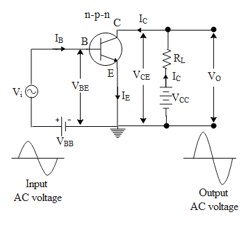
It is called the common-emitter configuration because ignoring the power supply battery both the signal source and the load share the emitter lead as a common connection point shown in the figure below. Amplifier is an electronic circuit that controls a large output signal using a small input signal. Transistors are used either as a switching or amplifying purposeThere are many types of transistorsThey are given below. A load resistance of 800 Omega is connected in the collector circuit and the voltage drop across it is 08 V. A Common Emitter Amplifier Is Designed With N P N Transistor Alpha 0 99 The Input Impedance Is 1 K W And Load Is 10 K W The Voltage Will Be.
 Source: instructables.com
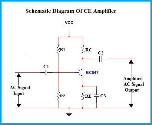
It will be enough to call t. This can have a few extra components added to enable it to become an AC coupled amplifier with DC biasing and emitter bypass resistor. Holes move from emitter to base. In common emitter transistor configuration input is applied between base-emitter junction. Diy A Basic Common Emitter Amplifier For School Studying 6 Steps Instructables.
 Source: instructables.com
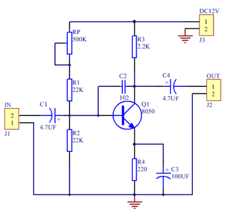
This can have a few extra components added to enable it to become an AC coupled amplifier with DC biasing and emitter bypass resistor. This can have a few extra components added to enable it to become an AC coupled amplifier with DC biasing and emitter bypass resistor. This electronics video tutorial provides a basic introduction into the common emitter amplifier which uses a NPN bipolar junction transistor. In active region the NPN transistor acts as a good amplifier. How To Design Common Emitter Amplifier 7 Steps With Pictures Instructables.
 Source: electrical4u.com
12 volts are common for a common emitter voltage amplifier. Practical Common-Emitter Amplifier Current Source. Lets take a closer look at common-emitter transistor amplifiers and discuss some things designers should consider during the common-emitter transistor. Common-Emitter One of the simpler transistor amplifier circuits to study previously illustrated the transistors switching ability. Common Emitter Amplifier Electrical4u.
 Source: youtube.com
Lets take a closer look at common-emitter transistor amplifiers and discuss some things designers should consider during the common-emitter transistor. I C β I B. The output is taken from a collector-base junction. Answer 1 of 5. A Common Emitter Amplifier Is Designed With Npn Transistor Alpha 0 99 The Input Youtube.
 Source: transistoramp.de
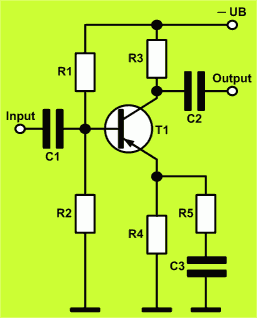
Practical Common-Emitter Amplifier Current Source. Common-emitter configurations are the most widely used type of transistor amplifier due to their high-efficiency and positive gain greater than unity. The common emitter configuration lends itself to voltage amplification and is the most common configuration for transistor amplifiers. Electrons move from base to collector. How To Design A Transistor Amp In Common Emitter Configuration With Transistoramp 1 1 Software.

Because CE amplifier have greater efficiency in increasing voltage and current of AC signalThe common emitter amplifier is one of the most common transistor amplifier configurations. Amplifier is an electronic circuit that controls a large output signal using a small input signal. In a common emitter NPN transistor the relation between collector current and emitter current is given as. Practical Common-Emitter Amplifier Current Source. A Common Emitter Amplifier Circuit Built Using An Npn Transistor Is Shown In The Figure Its Dc Current Gain Is 250 Rc 1 Kw And Vcc 10 V Sarthaks Econnect Largest Online Education Community.
 Source: electronics-tutorials.ws
Here we especially talk about common emitter configuration of bjt. Practical Common-Emitter Amplifier Current Source. This common-emitter amplifier is coupled to the emitter-follower amplifier designed in the Class A NPN Emitter-Follower Amplifier lab so it is recommended that this lab remain assembled on the solderless breadboard until completion of that lab. In active region the NPN transistor acts as a good amplifier. Npn Transistor Tutorial The Bipolar Npn Transistor.
 Source: in.pinterest.com
Common-emitter configurations are the most widely used type of transistor amplifier due to their high-efficiency and positive gain greater than unity. In common emitter transistor configuration input is applied between base-emitter junction. A common emitter amplifier is designed with NPN transistor alpha099. Choose a transistor The prototype amplifier for this exercise used a NPN small signal transistor such as the 2N3904 but other similar transistors should work equally well. Pin On Audio Amplifier.
 Source: electronics-tutorials.ws
Holes move from base to emitter. The output is taken from a collector-base junction. Choose a transistor The prototype amplifier for this exercise used a NPN small signal transistor such as the 2N3904 but other similar transistors should work equally well. Well basically Grounding in this case just means the point in the circuit the designer decided to call zero volts and use as a reference voltage when measuring voltages elsewhere in the circuit - it does not imply an actual connection to the earth. Common Emitter Amplifier And Transistor Amplifiers.
 Source: electronics-tutorials.ws
The objective of this experiment is to design a common emitter amplifier using a bipolar junction transistor and to study the characteristics of the designed amplifier. Well basically Grounding in this case just means the point in the circuit the designer decided to call zero volts and use as a reference voltage when measuring voltages elsewhere in the circuit - it does not imply an actual connection to the earth. Holes move from emitter to base. I C β I B. Common Emitter Amplifier And Transistor Amplifiers.
 Source: br.pinterest.com
Common-emitter configurations are the most widely used type of transistor amplifier due to their high-efficiency and positive gain greater than unity. The output is taken from a collector-base junction. In active region the NPN transistor acts as a good amplifier. The input impedence is 1k Komega and load is 10 Komega. Proud To Be An Electronics Engineer Electronic Engineering Transistors Electronics.


